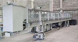
Tilting Flow Channel, 300mm wide
OSC77FD530HF
Features
-The channel is designed for studying the hydraulic flow phenomenaUnder Frame
-The channel bed is an invert which rests on an H-beam under frame
-The invert has screws at interval for vertical and side adjustment of the invert to ensure that the channel bed is strictly straight an level through out the full length
-The length of the H-beam is about 6m
-This simplifies site installation as there is only one joint and is easier to ensure alignment of the channnel
-The H-beam is supported by a fulcrum at one end and an adjustable height support at the other end
Slope Adjustment
-The adjustable height supports use twin screw
-Each screw is driven by a worm and wheel gear box with a common motor
-A slope scale is provided at one end of the flume
Side Walls
-For safety reasons, the side walls are made of tempered glass or clear acrylic
-The walls are supported at interval by brackets with screw adjustment to ensure that the channel wall is straight and vertical
-Further, a set of small adjusting screws along the edge of each glass plate for fine adjustment is also provided to ensure that the walls are vertical, parallel and straight throught out the channel length
Instrument Carriage
-Top rails made of stainless steel tubes are attached to the top angle on each wall of the channel
-Screws supporting the rails can be adjusted to ensure uniform height and in a straight line
-A scale graduated in mm is attached along the full length of one top angle of the walls
-The instrument carriage is motorized
-Power out is available on the carriage
Head Tank
-The head tank is made of stainless steel and its sides and bottom are curved to ensure smooth flow into the channel
-Perforated plates are also provided in the head tank to further smoothen the flow
Head Tank
-The storage tank has adequate water to fill the full channel
-The standard storage tank is a stainless steel tank with mobile ladder for model installation
Circulating Pump
-The pump seal is mechanical
-A geared butterfly valves is provided for accurate flow control
Flow Measurement
-A paddle wheel type flow sensor with two indicators, front and rear of the channel, is used for easy observation on flow adjustment
-A water meter is available as an option and may be used as reference for flow indicator setting later
Model and Accessories
-All accessories and models have side seals to ensure no water seapage or leakage through the side of the models A wide variety of models and accessories are available as an option
| Model | OSC 77FD 530HF | ||||||
| Flume dimensions | 30cm wide, 45cm high and 12m long | ||||||
| Tilting adjustment | -1% to +3% | ||||||
| Side walls | 6mmm tempered glass or 10mm clear acrylic | ||||||
| channel bed | Stainless steel | ||||||
| Instrument trolley | Motorized | ||||||
| Storage tank | Stainless steel | ||||||
| Head tank | Stainless steel with stilling baffles | ||||||
| Sluice gate | Stainless steel, rack and pinion type, built-in at both ends of flume | ||||||
| Circulating pump | 5.5kW with a maximum flow rate over 30 lps | ||||||
| Flow measurement | Flow sensor and indicators | ||||||
| Power supplu | 380V, 3Ph 50Hz or as required | ||||||
| Size | Approx. 250 x 1400 x 200 cm | ||||||


 pdf brochure